SensorFX Capabilities
Physically Accurate Sensors
Learn all about DI-Guy by clicking through the tabs below or download the SensorFX Capabilities document.
SensorFX Includes
- Material Library - Surface optical, thermo-physical, and EM material property data library
- SigSimRT - Spectral Signature Synthesis and MODTRAN-based Atmospherics
- SenSimRT - Advanced EO/IR Sensor Effects
Sensor Types Modeled
- FLIRs / Thermal Imagers: 3-5 & 8-12μm
- Image Intensifiers / NVGs: 2nd & 3rd Gen
- EO Cameras: Color CCD, LLTV, BW, SWIR
Models & Terrain
- Material classified DI-Guy Character Set
- Material classified 3D Vehicle Set
- Material classified VR-Village Terrain DB
Sensor Effects
- Optics
- Detector FPA
- White noise (NET)
- 1/f noise
- I2 (NEI)
- Signal processing
- Display
- AGC
- Gain/level
- Light-point haloing
Sensor Effects: Optic Settings
- Aperture Shape: Circular vs rectangular.
- Aspect Ratio: Ratio between horizontal and vertical Instantaneous Field Of View (IFOV).
- Changes made here are most noticeable when blur is high.
- Aperture Diameter:
- Units are in millimeters (mm).
- Used in diffraction calculations.
- Lower values produce more diffraction spreading (blur).
- Blur Spot Diameter: This quantity [mrad] is a measure of the amount of spherical aberration, and thus the focusing power of the lens. The more this number varies away from the focal point the more blur in the scene.
- F-Number: Non-editable field. It is calculated based on the focal length and aperture diameter.
- Focal Length: Non-editable field. It is calculated based on the FOV and aperture Parameters. Units are cm.
- Halo Threshold: A “cutoff limit” as to which light sources produce halos. If this value is higher, only stronger light sources will produce halos.
- Halo Radius: Determines the overall maximum size of the Halo.
- Halo Intensity: Determines the maximum brightness of the Halo.
Sensor Effects: Detector Settings
- Dwell Time: Dwell time is the time [µsec] over which the post-detector electronics integrates the detector output voltage.
- Temporal NEdT: [degK] “noise-equivalent delta-temperature”.
- % Fixed Pattern (Noise) : Unwanted signal component that is usually constant or very slowly changing with time.
- % Poissan (Noise) : Also known as “shot” noise : statistical fluctuations in charge carrier number.
- % 1/f (Noise) : Also known as “flicker” or ‘pink noise”, this occurs in any biased detector and is a thermo-mechanical effect related to lack of material homogeneity or transistor recombination.
- Noise Frequency Exponent: [unitless] Also known as “beta”, this is the exponent of the 1/f noise power spectrum.
- Noise Frequency Knee: The frequency above which 1/f noise is overshadowed by thermal or statistical noise from other processes.
- Horizontal Detector Pitch : The horizontal distance between detector centers [mm], used in determining focal length.
- Vertical Detector Pitch: The vertical distance between detector centers [mm], used in determining focal length.
- Background Temperature : The effective temperature [degK] of the ambient background.
- Detector Pixel Fill : [%] Term of measurement of FPA performance, which measures how much of the total FPA is sensitive to IR energy.
- FPA (Focal Plane Array) Operability: This indicates the effectiveness of the detector and 100% would be fully functional and as the operability percentage drops the image quality drops.
Sensor Effects: Electronics Settings
- Frame Rate : The frame rate parameter is used to determine the change in temporal noise per frame.
- Pre-Amp On Frequency: Frequency at which amplification of the signal occurs after conversion to a voltage.
- Post-Amp Off Frequency: Frequency at which amplification of the signal ceases.
- Gain: This is the manual gain value. The Effects section sliderr will scale the gain from 0-100% of this value.
- Level: This is the manual level and is added to the value from the Effects section, so if you are using a sliderr for that, then this would be set to zero. This could probably be left out of a GUI if the sliderr was being used.
- Max/Min AGC: The maximum and minimum (i.e. range of) values the Automatic Gain Control will take into consideration when determining gain of the scene.
SigSimRT – Radiometric Image Generation
By JRM Technologies
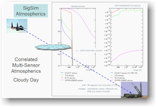
SensorFX uses JRM Technologies' SigSimRT to generates physically accurate sensor images for VR-Vantage applications.
By applying advanced signature synthesis and atmospheric propagation models, SigSim’s ultra-fast algorithms credibily render the synthetic environment in any waveband within the 0.2 - 25.0um spectrum (UV, visible, near-IR, thermal-IR) and for arbitrary RF frequencies.
On-the-fly physics-based sensor modeling and an open standards material classification approach make it an ideal for real-time sensor applications.


SenSimRT – Sensor Device Modeling
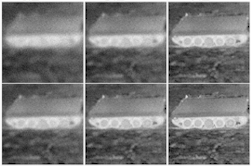
SensorFX uses JRM Technologies' SenSimRT to model the detailed specifications of the sensing device and apply the correct effects to the imagery produced by SigSim.
SenSim is an advanced sensor modeling toolkit and run-time library for real-time sensor effects simulation of any optical sensor in the EO or IR passband. It provides engineering-level sensor modeling of the optics, detector, electronics, and display components, simulating appropriate Modulation Transfer Functions (MTFs), detector sampling, noise, non-uniformity, dead-detectors, fill-factor, 1/f and white noise, pre-and post-amplifiers, and displays.
SenSim can use the actual sensor component specifications to provide the most realistic sensor visualization experience.


GenesisMC - Material Classification
GenesisMC (not included with SensorFX) is an easy-to-use, GUI-based tool for high-confidence material-classification. Sensor simulations need to know what things are made of, not just what color they are. GenesisMC helps you map the textures and imagery in your synthetic environment to high fidelity material properties.
Its semi-automated approach speeds the process along, using smart reverse-signature predictive and spatial algorithms to predict the most likely surface material.
- A Comprehensive Material Classification System
- Advanced Algorithms
- Semi-Automated Classification
- Validation Tools
- Signature Prediction and Spectral Matching
- Dynamic Heating & Cooling of Active Thermal Regions
- Extensive Material Library
- Supports Industry Standard Source Data

Material Classification on Demand
- VR-Vantage material classification on demand (MCOD) provides automatic material classification using vector shape-files, and combines them with an intensity-modulated image to produce material encoded textures used in the real-time sensor rendering. The material encoded textures use JRM’s Eigen material technique, which provides excellent rendering capabilities with the ability to mimic an unlimited number of material systems through the combination of multiple eigen materials.
The process is done automatically as the data is paged in from the server, and once the material textures have been generated, the texture array images are saved to the standard osgEarth file cache ready for fast loading on subsequent runs.
The MCOD process:
• Processes any number of vector shape-files as raster images for each LOD. These shape-files represent material features (for example, roads, building footprints, water, and so on.)
• Combines the image textures to produce a per-pixel intensity modulation that maintains the spatial variation.
• Generates the material classified texture layers that are processed in real-time to calculate sensor wavelength-specific output using JRM’s sensor suite.

